Shape Optimization of Gravity Base Wind Turbine Foundations
The gravity-base (or inverted-T) foundation is the predominant choice for supporting onshore wind turbine towers. It is a shallow foundation system that bears about 7 to 12 feet below grade and relies on gravity for overturning stability, hence, the gravity-base connotation. Gravity can be achieved in many different ways as it simply means increasing the weight of the components that contribute to foundation stability through gravity. This Segway is a hint that points to the shape optimization strategies described in this blog and the limits of such strategies.
Historical Account
In 2006, while working in an owner engineering role, I reviewed a wind turbine foundation consisting of a square, uniform thickness, reinforced concrete slab (Figure 1). The design was simple and passed the technical review checks but was utterly inefficient in terms of material usage. Reinforcement bars are straight and of the same length; concrete is easy to form and pour. However, the quantities are larger than necessary which defeats the purpose of reducing the carbon footprint of such foundations.

Figure 1: Flat slab foundation: simple to detail and construct but utterly inefficient
That 2006 design was the last time I have come across such a wind turbine foundation and a lot has changed since then. Practitioners quickly figured out that soil backfill over the foundation weighed almost as much as concrete but was much cheaper. In fact, soils excavated during construction needed a place to go and placing and compacting them back on top of the foundation was the obvious solution. Logically, the truncated pyramid shape shown in Figure 2 would be the next best thing compared to the flat slab of Figure 1. However, in my twenty years of practice, I have not seen a truncated pyramid Wind Turbine Generator (WTG) foundation. Instead, the industry standardized on the octagonal shape shown in Figure 3.

Figure 2: Truncated pyramid shape
Some reasons the octagonal shape of Figure 3 became so popular for over a decade (2006-2016) include:
The bottom mat of reinforcement consists of orthogonal straight bars that are easy to place, especially since they are placed under the anchor bolt cage as is done in North American practice (we will come back to why this may not be the best option in another blog).
Top mat of reinforcement is also orthogonal and consists of straight bars only bent at two spots to follow the top surface geometry.
Bottom edge forming consists of identical straight segments.
There are however a few drawbacks of the popular octagonal geometry shown in Figure 3:
Since the top mat reinforcement is orthogonal and is required to go through the anchor bolt cage, there are inevitable clashes of these top mat bars with the anchor cage bolts and pedestal vertical reinforcement.
As will be shown later, this shape can be optimized further.

Figure 3: Octagonal shape popular for over a decade (2006-2016)
Working for a leading renewable energy developer and EPC contractor for 10 years, I was at a privileged position where my team could design the foundation in-house and oversee its construction to learn first hand about challenges and opportunities. I knew we could improve on the popular octagonal shape of Figure 3 and we came up with the more optimized octagonal shape shown in Figure 4. This design was an improvement because:
The top mat reinforcement was no longer orthogonal but two sets of radial and circumferential bars. Hence, the clashes between these bars and the anchor cage bolts were avoided since the radial bars would just slip between the anchor bolts.
The simplicity of the orthogonal bottom mat reinforcement was retained.
The shape reduces the volume of concrete further by avoiding the “humps” in the more popular octagonal shape of Figure 3.

Figure 4 - Improved octagonal shape.
After building a few projects using the more optimized octagon of Figure 4, the direction I was getting from the field pointed clearly towards the perfectly round shape shown in Figure 5. The round shape offered further reductions in concrete by getting rid of the humps and the octagon apexes. This shape also entailed using radial and circumferential reinforcement for both the top and bottom mats, even though an orthogonal bottom mat could still be used. This radial / circumferential bottom mat arrangement was met with mixed feedback from EPCs and subcontractors. Subcontractors welcomed it without reservations but a few EPCs mentioned the additional cost of continuous bending of the larger circumferential bottom mat bars and, for a few years, favored sticking with the orthogonal shape of Figure 3. By around 2020, the round shape of Figure 5 became industry standard and I can confidently claim the credit for this industry shift.
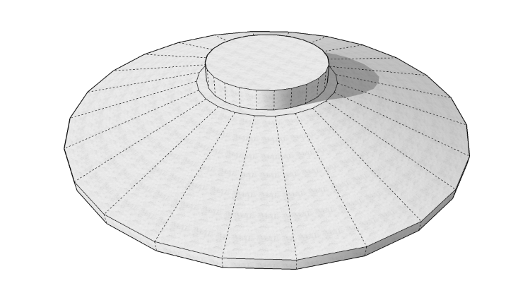
Figure 5 - The optimal round shape most widely used today
Going Beyond the Round Shape
For illustrative purposes, concrete volume is calculated for foundations with different shapes but with the following common dimensions:
Width of 20 meters,
Pedestal diameter of 6 meters,
Pedestal height of 1.5 meters,
Middle slab thickness of 2 meters, and
Edge thickness for a tapering slab of 0.5 meter.
As shown in Figures 6 and 7, the shape optimization exercise seems to level off with the round foundation shape.

Figure 6 - Shape optimization diminishing returns
With the larger 4.5 to 6.5 MW land-based wind turbines coming to the market today, it is reasonable to wonder about the next ideas and innovations that can limit quantities, construction labor and the overall carbon footprint of the foundation. Namely, the challenge for the gravity-base system is being able to go beyond the shape optimization floor. There are several competing patented solutions out there and more are likely under development. We believe that reliability-based design in general and the patented d-RBD process are potential solutions.

Figure 7 - Beyond gravity base shape optimization