Large wind turbine gravity foundations are sometimes treated in simplified design calculations as essentially rigid plates resting on an elastic soil medium. That assumption is convenient. However, for foundations spanning tens of meters, subjected to very large overturning moments, and interacting with nonlinear soil contact, convenience does not necessarily represent the actual structural response. The vertical-displacement contours shown in the numerical model below illustrate why. They also highlight two closely related design quantities that deserve careful treatment: foundation tilt and foundation rotational stiffness.
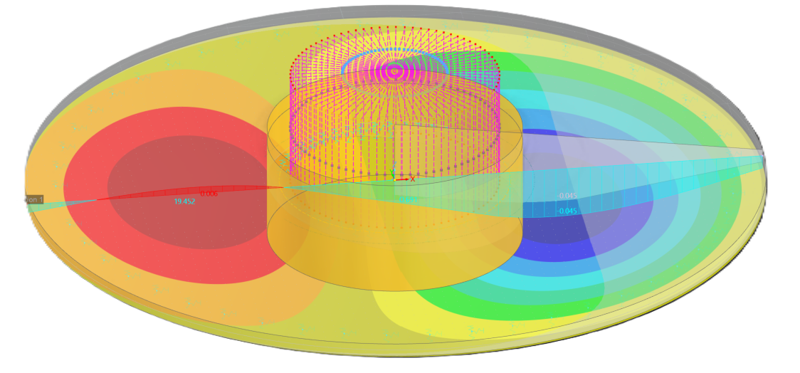
Vertical-displacement contours and centerline displacement profile for a large wind turbine gravity foundation under overturning load. Partial loss of contact develops on the uplift side, while compression and downward displacement occur on the opposite side. The nonlinear displacement profile, particularly the increased gradient beneath the pedestal, illustrates foundation flexibility and highlights why foundation tilt and effective rotational stiffness depend on how and where rotation is evaluated.
What the Displacement Field Is Telling Us
Under a large overturning moment, the response is clearly asymmetric.
On one side of the foundation, the model shows downward vertical displacement and continued foundation-soil contact. On the opposite side, the red region corresponds to essentially zero vertical displacement in the displayed contour range and, based on the contact-pressure results, a loss of contact or foundation lift-off.
This behavior is important because the foundation is no longer behaving like a rigid disk simply rotating about a single point. Instead, the foundation-soil system is deforming.
Even more revealing is the vertical-displacement profile across the foundation centerline. The most significant change in the displacement gradient occurs near and immediately beneath the pedestal. In other words, the deformation profile is not a straight line across the foundation diameter.
If the foundation behaved as an ideal rigid body, the vertical-displacement profile associated with rotation would be approximately linear:
w(x) = w0 + θx
Therefore:
θ = dw/dx
would be essentially constant across the foundation.
The numerical results show a different response: the slope varies significantly with position. That is direct evidence of foundation flexibility.
Why This Matters for Foundation Tilt
A common simplified approach is to calculate foundation rotation from the difference between vertical movements at two widely separated locations, such as opposite edges of the foundation:
θglobal ≈ (wR − wL)/D
where D is approximately the foundation diameter.
This quantity describes an average or secant rotation across the foundation. It does not necessarily describe the local rotation experienced by the wind turbine tower at the pedestal.
For turbine performance, the quantity of interest is generally much closer to the rotation of the structural support immediately beneath the pedestal:
θpedestal ≈ (dw/dx)pedestal
The distinction can become significant when the foundation is flexible.
The steepest portion of the displacement profile occurs in the pedestal region. Consequently, calculating tilt using displacement differences near the outer edges can average the deformation over the entire foundation diameter and potentially mask a much larger local structural rotation beneath the tower.
This is not merely a mathematical distinction. It changes what engineers should extract from their models when evaluating turbine-support rotation.
Foundation Rotational Stiffness Deserves the Same Scrutiny
The same observations have an important implication for foundation rotational stiffness.
Wind turbine analyses commonly require foundation stiffness parameters to represent the support condition at the tower base. The basic effective rotational stiffness is:
Kθ = M/θ
where:
Kθ is the effective rotational stiffness;
M is the applied overturning moment; and
θ is the corresponding rotation.
The units of rotational stiffness are moment per radian, commonly kN-m/rad or MN-m/rad.
Global Rotational Stiffness
For a foundation treated as rigid, rotation is commonly estimated from the differential vertical displacement between two points separated by a distance L:
θsec ≈ (w2 − w1)/L
Combining this expression with the basic stiffness relationship gives:
Kθ,global ≈ ML/(w2 − w1)
This value represents a global or edge-to-edge rotational stiffness of the combined foundation-soil system.
Local Pedestal Rotational Stiffness
For a flexible foundation, the displacement profile w(x) is curved and the rotation varies spatially. The local rotation is represented by the slope of the displacement field:
θ(x) = dw(x)/dx
The rotational stiffness associated with the tower-support region may therefore be expressed as:
Kθ,pedestal = M/θpedestal
with:
θpedestal ≈ (dw/dx)pedestal
When rotation is evaluated over the finite pedestal diameter Dp, an effective pedestal rotation can be calculated using:
θpedestal ≈ (wR − wL)/Dp
where wR and wL are vertical displacements evaluated at appropriately selected locations on opposite sides of the pedestal.
This finite-difference form can be useful for extracting an effective tower-support rotation from numerical-model results.
Secant and Tangent Stiffness
For nonlinear soil-structure interaction, rotational stiffness should also be associated with the load level at which it is evaluated.
The secant stiffness between two load states is:
Kθ,sec = (M2 − M1)/(θ2 − θ1)
If the reference state is the origin, the expression reduces to:
Kθ,sec = M/θ
The tangent rotational stiffness at a particular point on the moment-rotation curve is:
Kθ,tan = dM/dθ
These equations make an important point: rotational stiffness is inseparable from the definition of rotation used to calculate it.
For a flexible foundation, Kθ,global and Kθ,pedestal can be materially different because the associated rotations are not necessarily the same.
If an edge-to-edge secant rotation is used, the calculated stiffness represents the global response of the foundation-soil system. If the turbine responds to the local rotation beneath the pedestal, that global stiffness may not represent the actual support condition experienced at the tower-foundation interface.
Why Foundation Stiffness Can Be Load-Dependent
The distinction becomes even more important once uplift develops. As foundation-soil contact changes, the effective bearing area and reaction distribution also change. The relationship between overturning moment and rotation therefore does not necessarily remain linear.
Rather than treating foundation stiffness as a single immutable constant, advanced analysis can characterize the complete moment-rotation response.
For integrated turbine-foundation analyses, engineers should clearly define:
where rotation is measured;
whether stiffness represents the soil alone or the combined soil-foundation system;
whether the reported stiffness is secant or tangent stiffness;
the load level at which stiffness is evaluated;
whether foundation-soil separation is permitted;
whether the stiffness represents global foundation behavior or local pedestal behavior; and
whether the same rotation definition is used in the foundation model and the global turbine model.
A stiffness value without these definitions can give a misleading impression of precision.
The Foundation Is Part of a Coupled System
Large wind turbine foundations are particularly challenging because several mechanisms interact:
foundation plate and pedestal stiffness;
soil stiffness and nonlinear soil response;
compression-only foundation-soil contact;
redistribution of bearing pressure as overturning moment increases;
partial loss of contact and uplift;
radial and circumferential bending of the foundation;
shear transfer between the pedestal and foundation;
the geometric relationship between pedestal diameter, foundation diameter, and foundation thickness; and
the interaction of vertical load, horizontal load, and overturning moment.
Once partial contact develops, the problem becomes even more nonlinear. The active bearing area changes as load changes. Structural deformation influences the contact-pressure distribution, while the changing contact-pressure distribution simultaneously influences structural deformation.
This is fundamentally a soil-structure interaction problem, not simply a footing-bearing-pressure calculation.
The Limitations of Closed-Form and Empirical Methods
Closed-form equations, empirical relationships, and hand calculations remain extremely valuable engineering tools. They provide transparency, enable independent checks, and are useful for preliminary sizing and verification.
The concern arises when simplified methods become the sole basis for predicting the behavior of a highly nonlinear foundation system.
A simplified calculation may produce a credible estimate of average foundation rotation or effective stiffness while failing to capture:
localized curvature beneath the pedestal;
changing foundation-soil contact conditions;
uplift zones;
nonlinear redistribution of soil reaction;
flexibility of the foundation plate;
load-dependent rotational stiffness; and
differences between global foundation rotation and local tower-support rotation.
The lesson is not that hand calculations are obsolete. The lesson is that their assumptions must be consistent with the structural behavior being evaluated.
What Advanced Numerical Modeling Should Evaluate
A properly constructed finite-element or comparable advanced numerical model allows the engineer to examine quantities that simplified equations cannot readily reveal.
For a wind turbine gravity foundation, the assessment should include more than maximum stress or maximum displacement.
Foundation-Soil Contact Pressure: Determine where the foundation remains in compression and how the active contact area changes under overturning load.
Uplift and Contact Status: Identify where separation occurs and how loss of contact affects the remaining bearing-pressure distribution.
Vertical-Displacement Profiles: Rather than reporting only isolated maximum and minimum displacements, extract displacement profiles along strategically selected centerlines passing through the pedestal.
Local Rotation Beneath the Pedestal: Evaluate the displacement gradient in the region that directly supports the tower.
Foundation Curvature: A nonlinear displacement profile reveals structural bending that cannot be represented by a single rigid-body rotation.
Moment-Rotation Behavior and Effective Stiffness: Evaluate how rotation develops with applied moment and whether the effective rotational stiffness changes as soil contact redistributes or uplift develops. Where stiffness is supplied to a global turbine model, confirm that the extracted stiffness corresponds to the rotation definition used at the tower-foundation interface.
Sensitivity to Soil and Interface Assumptions: Evaluate the response using credible variations in soil stiffness, foundation-soil interface behavior, structural properties, and other governing parameters.
A More Sophisticated Model Is Not Automatically a Better Model
Finite-element analysis should not become a substitute for engineering judgment.
Advanced models can produce highly detailed contour plots while still producing incorrect results if the boundary conditions, soil properties, mesh density, interface behavior, structural stiffness, or application of load are inappropriate.
A defensible analysis should combine three levels of engineering:
Hand Calculations → Numerical Modeling → Engineering Interpretation
Simplified calculations provide bounding checks and physical intuition. Numerical analysis captures behavior that simplified methods cannot. Engineering judgment determines whether the calculated results are physically reasonable.
That combination is more powerful than relying exclusively on either hand calculations or finite-element analysis.
A Better Definition of Foundation Tilt and Stiffness
Engineers should be precise when using the terms foundation tilt and foundation stiffness.
For a flexible foundation, there may not be one unique rotation representing the entire structure. Similarly, a single rotational stiffness value may not fully characterize the response over all load levels.
The following quantities should be distinguished:
Global or secant foundation rotation: Rotation derived from displacement over a large portion of the foundation.
Local foundation rotation: Rotation derived from the slope of the displacement profile at a specific location.
Pedestal or tower-support rotation: Rotation representing the response transmitted into the turbine support.
Global rotational stiffness: Stiffness based on the overall foundation-soil response.
Tower-support rotational stiffness: Stiffness based on the moment-rotation response at the pedestal interface.
Secant rotational stiffness: Average stiffness evaluated over a specified moment-rotation interval.
Tangent rotational stiffness: Incremental stiffness evaluated at a particular point on the moment-rotation curve.
For a large flexible foundation, these quantities do not have to be equivalent.
The distinction becomes particularly important when foundation-rotation limits or stiffness parameters are checked against turbine-supplier requirements or incorporated into global turbine structural models.
The Engineering Takeaway
Large gravity foundations should not automatically be assumed to behave as rigid bodies.
When numerical analysis demonstrates appreciable foundation curvature, calculating rotation solely from differential settlement at opposite foundation edges may not capture the rotation occurring immediately beneath the pedestal. The same simplification can affect the rotational stiffness derived from that rotation.
For these complex structural systems, advanced numerical modeling provides the ability to see what simplified equations inherently average out:
foundation flexibility;
changing soil contact;
foundation uplift;
pressure redistribution;
localized pedestal rotation; and
load-dependent rotational stiffness.
Closed-form and empirical calculations remain indispensable for preliminary design and independent verification. However, when an engineering decision depends on the deformation or stiffness of a large wind turbine foundation, the analytical model should represent the physics of the foundation-soil system closely enough to distinguish global foundation response from the local response experienced by the tower.
The important questions are no longer simply:
How much does the foundation tilt?
What is the foundation stiffness?
The more meaningful question is:
Where is the rotation occurring, how does that rotation evolve with load, and what effective stiffness does the turbine actually experience at the tower-foundation interface?
Those questions deserve the appropriate level of numerical analysis.